
Start by printing out a wire length sheet.
Then after verifying the scale ruler, begin cutting your wires and pigtails to length.
Also cut the weapon motor and Weapon ESC to length.

Layout your additional connectors and electronics.
Component List:
2 pairs of 2mm bullet connectors
Fingertech Mini Power Switch
1 pair of MR30 connectors
1 male XT30 connector
1 Scorpion Nano ESC

Scorpion Nano Prep
In order to make the drive motors easily replaceable, we need to use JST 2pin connectors instead of the included wires on the Nano.
First, de-solder the 4 motor wires and 2 power wires on the Scorpion Nano.

Next, separate the red wires from the receiver pigtails. We will be removing these as we want to use a 5v weapon ESC BEC or a dedicated BEC.
Once the wires are separated, de-pin them from the black receiver connector housings.
Lastly, flip the board over and while gently pulling on the red wires, melt the solder holding the red wires to the board. The wires should easily come right out, be careful not to de-solder surrounding wires.

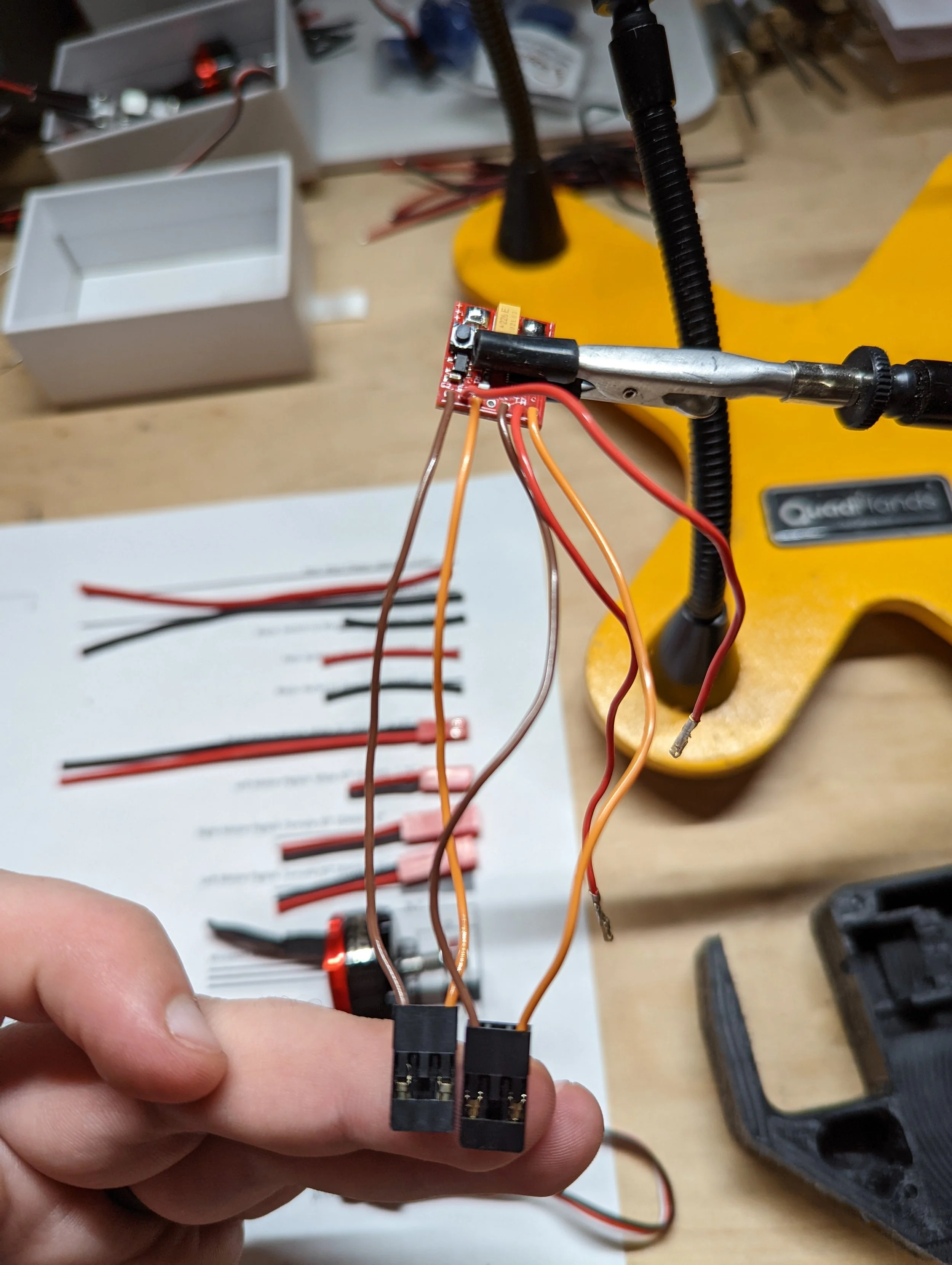

Now we need to add some wires back to the Scorpion Nano.
Start by stripping 1/8” to 3/16” of insulation off of your ESC side JST Pigtails.
Next tin the wires.
Now solder them to your Scorpion Nano in the pictured orientation. Be sure to note the polarity of the wires. This will ensure that if your spares won’t spin the wrong way!


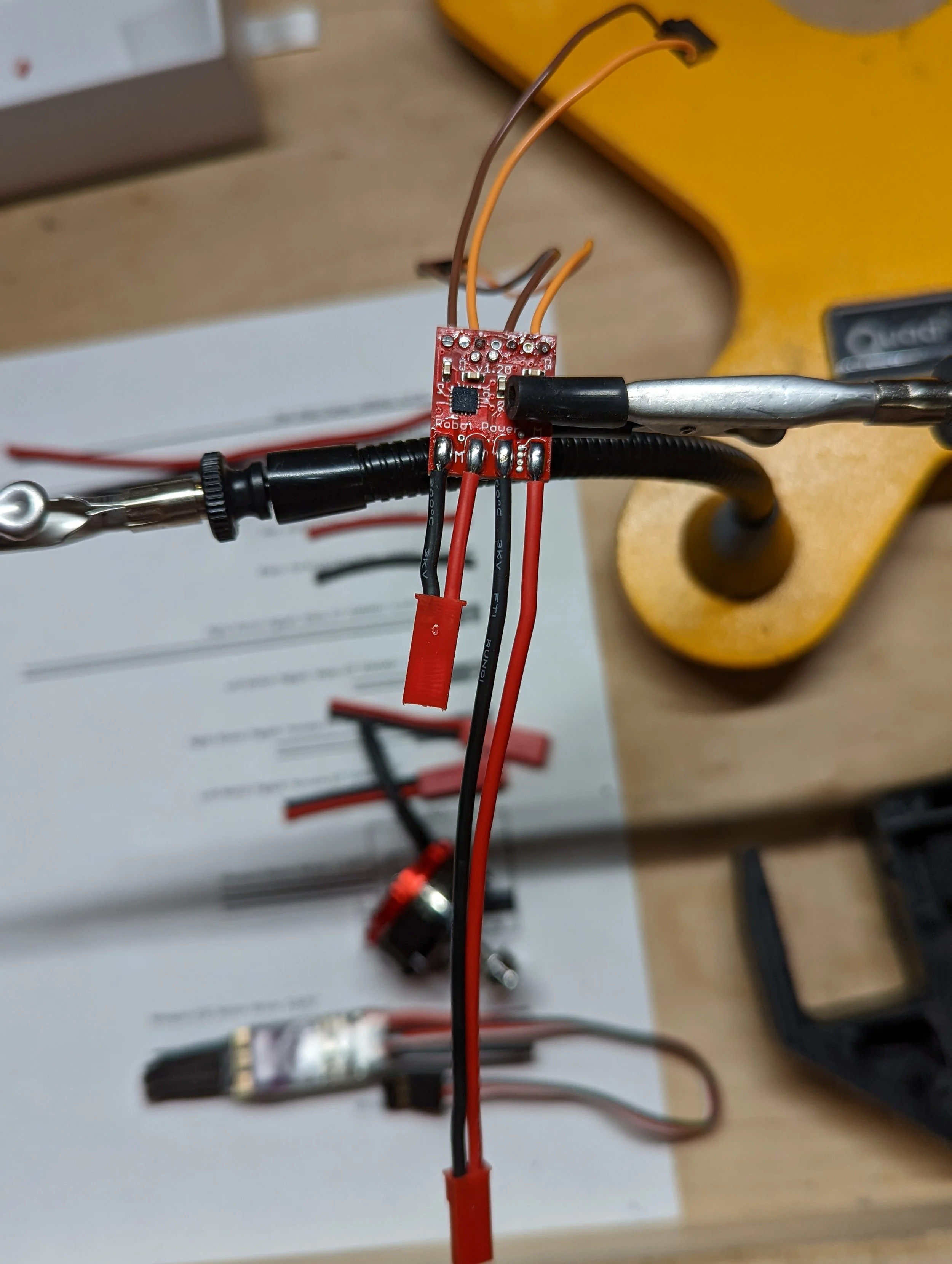
Next, grab your two 1.5” “Bullet to Drive ESC” wires, strip off 1/8” to 3/16” and tin them
Now flip those wires, strip the other end slightly longer, 1/4” and tin that side as well.
Next, solder the shorter end to your Scorpion Nano power pads.


Creating your power lead pigtail
Grab your two 4.375” Main Power Wires, strip about an 1/8” off, tin both the connector and wires.
Now solder them to the male XT30.
Be sure to add your heat shrink now!


Power switch
Next, add heat shrink on the negative wire of your power lead pigtail. If you forget this now, you can’t add it later!
Now strip both of the power lead pigtail ends about 3/16” and tin them both.
Tin the bottom of the lower power switch tab and solder your negative power lead pigtail wire to it. Orientation is important here, note that the switch screw is pointed downwards!
Now slide the heat shrink over the entire tab!
Now is also the perfect time to use a heat gun to shrink the heat shrink


Power switch part 2
Next take your 1.375” switch to weapon ESC wire and strip 1/8” off one side and about 3/16” off of the other.
Tin both sides of your wire and tin the top of the upper tab on your weapon switch.
Solder the wire to the top of your switch tab.
Now add heat shrink to the top tab.


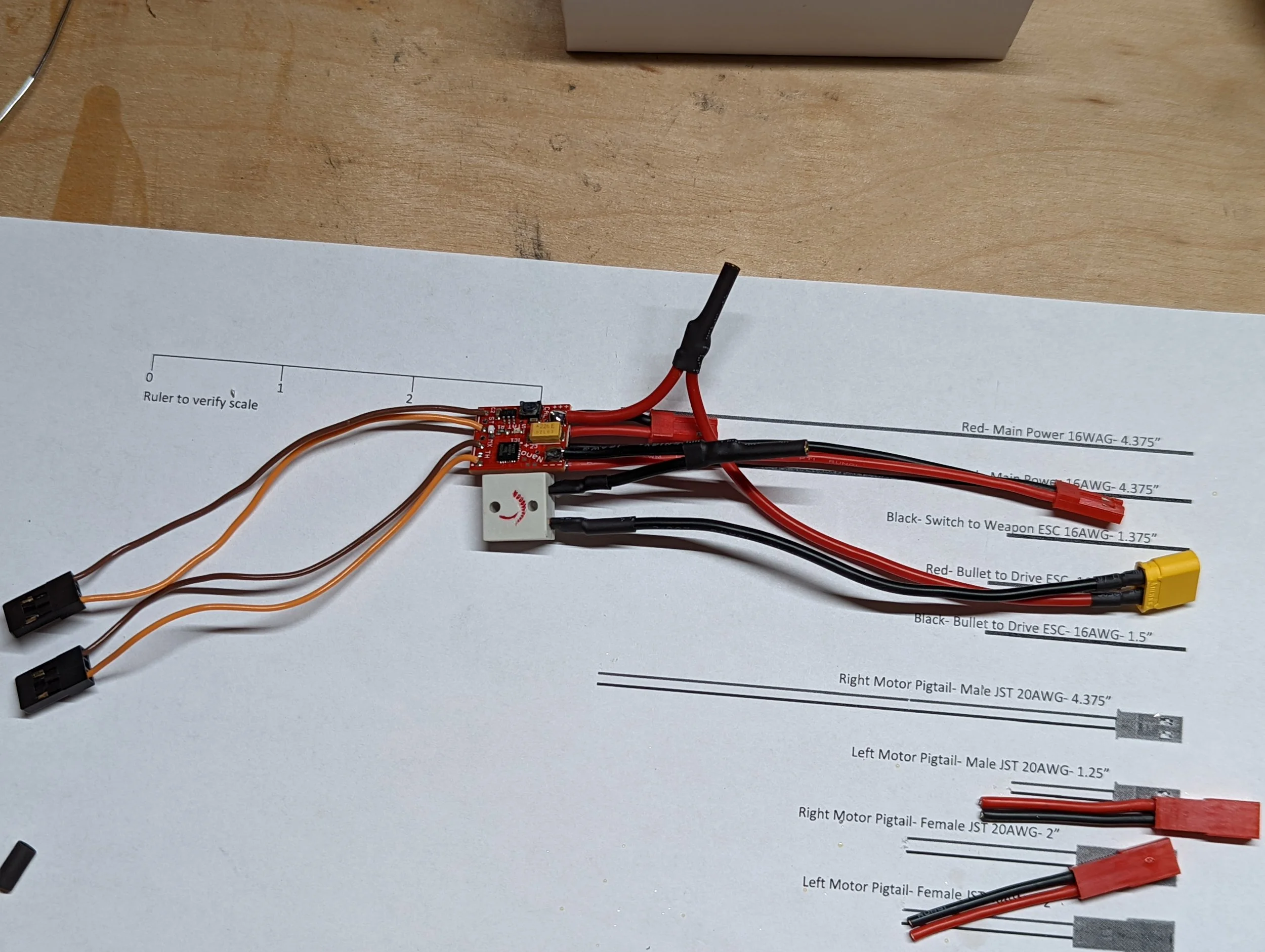
Progress Update:
At this point your harness should look like this! If it doesn’t, scroll back out and figure out what you missed!

Next we need to solder 2mm female bullet connectors to the positive “main power wire” and the negative “switch to weapon esc wire”.
Tin the female bullet connectors and solder the the wires to the bullets.


Time to finish your wiring harness!
This can be the trickiest part of the harness, where we connect the two halves we have been working on.
We need to solder the two power wires from the Scorpion Nano ESC to the outside of the female bullet connectors. Notice that I clamped both the wire and bullet connector in the leftmost picture. This will hold the wire inside the bullet connector while you solder the additional wire to the outside of the bullet.
Now add heat shrink to the entire joint and shrink!


Progress Update:
At this point your harness is complete and should look like this! If it doesn’t, scroll back out and figure out what you missed!
Preparing your weapon motor:
Strip an 1/8” of each of your weapon motor wires and tin each wire.
Now add about a 1/4” of heat shrink to each wire, be sure to get it as far down the wire as you can.
Now orient your male MR30 connector with the three on the left and 1 on the right. These numbers are fairly small just below the MR30 on the connector.
Now solder each wire to the connector, note the motor orientation when you do this, if you get this backwards your motor will spin backwards! Note that if you put too much heat into the wires you can shrink the heat shrink at the base of the wire!
Now shrink your heat shrink.


Preparing your weapon ESC:
Strip an 1/8” off of all 3 motor wires, both power wires and tin each wire.
Now add about a 1/4” of heat shrink to each motor side wire, be sure to get it as far down the wire as you can.
Now orient your female MR30 connector with the ONE on the left and THREE on the right. These numbers are fairly small just above the bullet connector tabs. Note the ESC orientation when you do this, if you get this backwards your motor will spin backwards!
Now solder each wire to the connector. Note that if you put too much heat into the wires you can shrink the heat shrink at the base of the wire!
Now shrink your heat shrink.
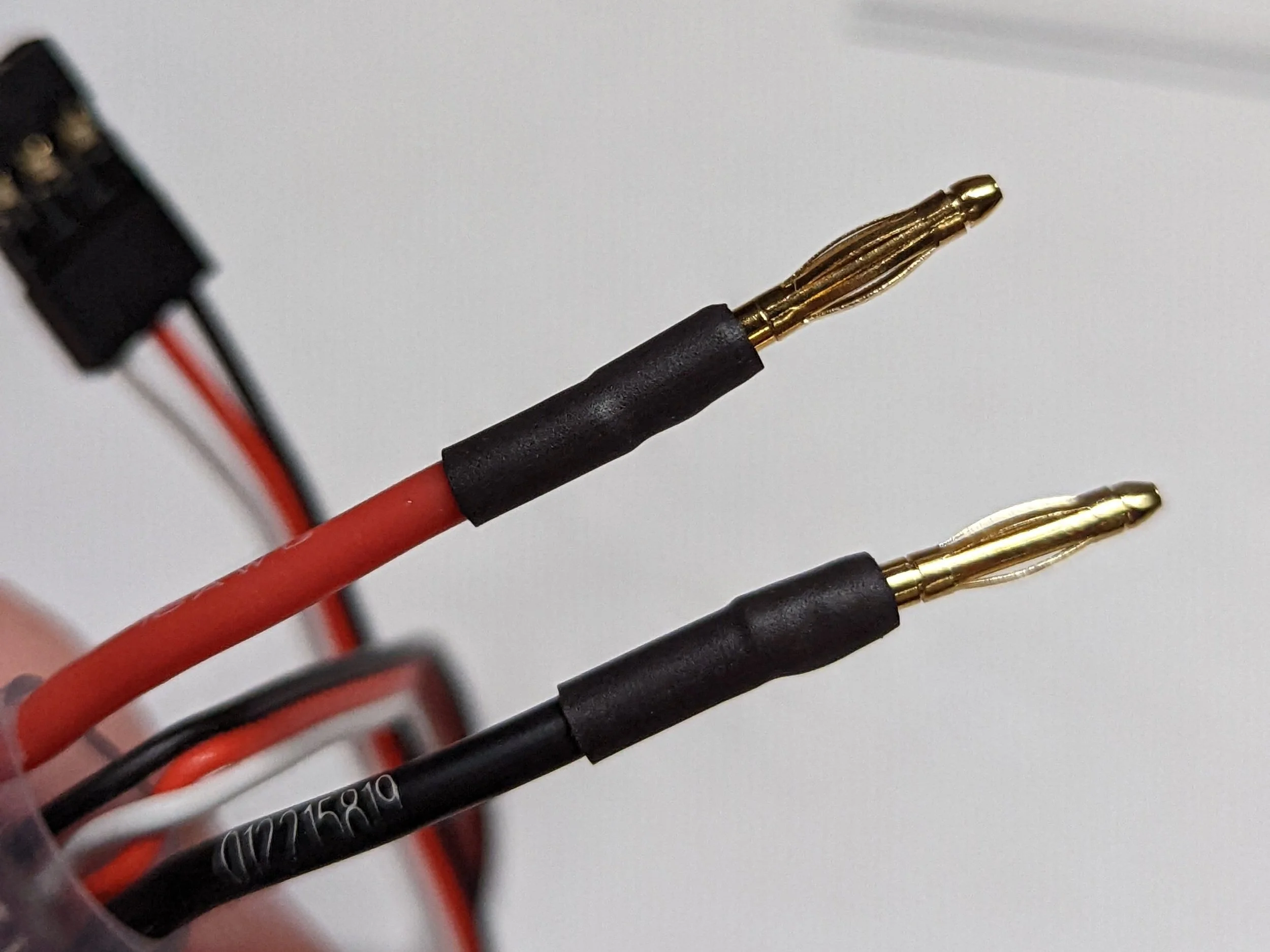
Next tin both your male bullet connectors and solder them to your ESC power wires.
Be sure to add heat shrink to
your male bullet connectors!


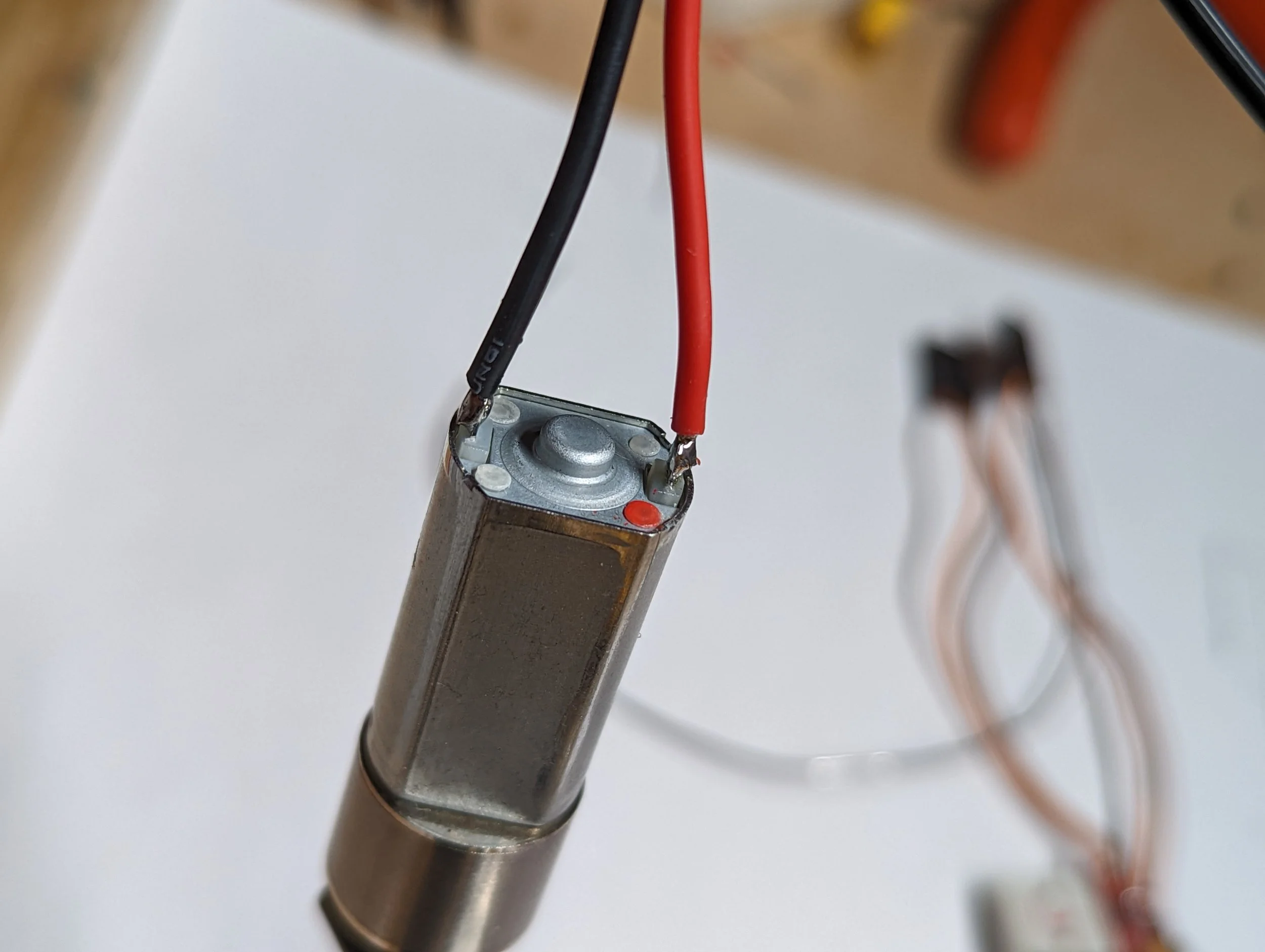
Drive Motor Prep:
Grab your motors, and male JST pigtails.
Strip about an 1/8” off of the pigtails and tin both the wires and motor tabs.
Solder the wires to the motor tabs.
Next I put a little bend in the tabs to keep the wire/tab away from the motor case.


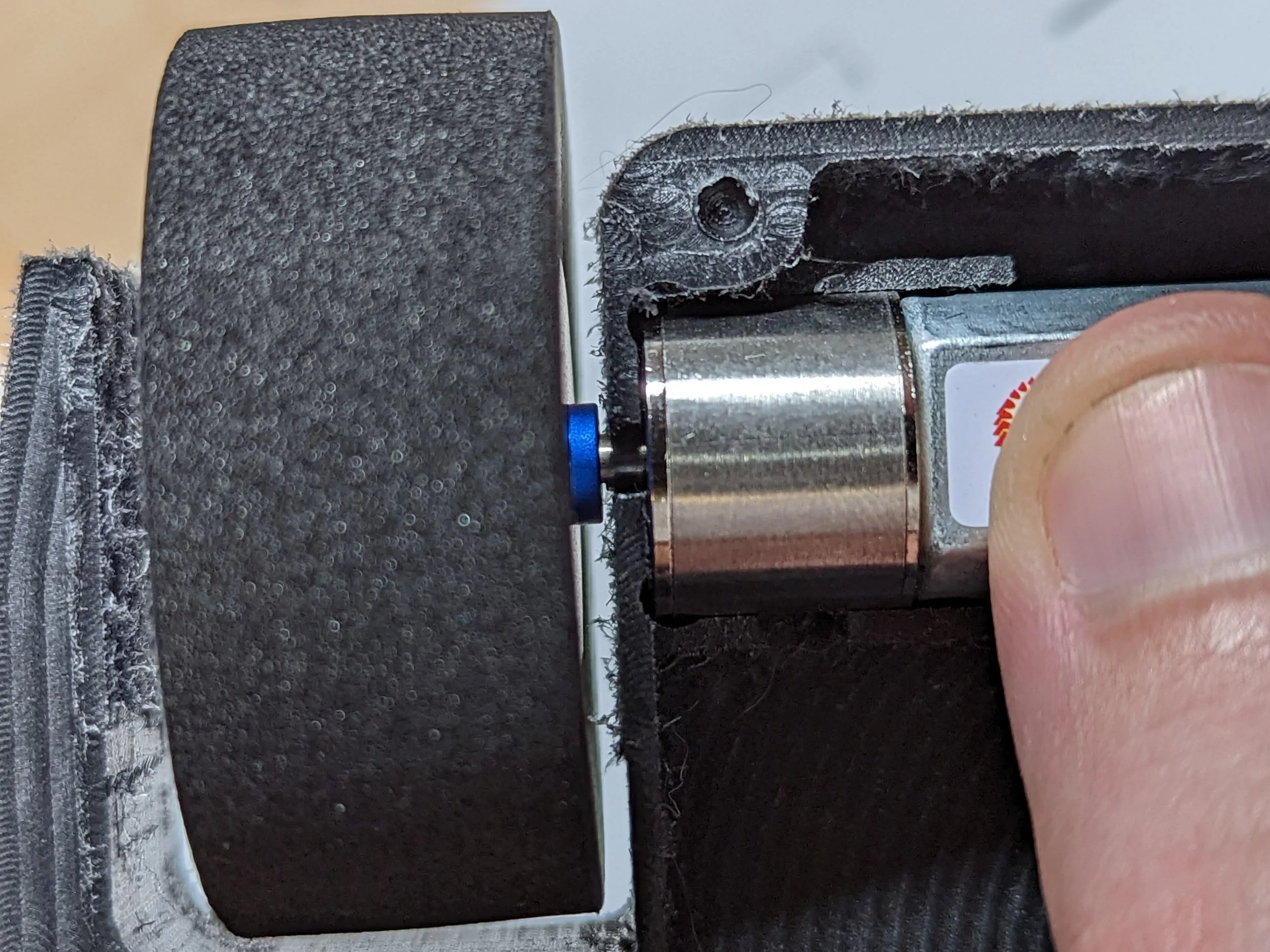
Next, we need to cut our drive motor shafts. I cut them to 9/16” from the face of the gearmotor.
After cutting the shafts we need to Loctite the gearbox to the motor. I use blue Loctite for these.
Now we can put on the wheel hubs, make sure to Loctite these as well. Make sure you have a little bit of clearance between the side of the chassis and the wheel hub!


Component Install:
When installing your drive motors, be sure to seat the rear of the motor by installing it at a slight angle before pushing the motor all the way in.
Next install your power switch by pressing it into the chassis slot.
Now route the main power leads and right motor pigtail through the wire channel with the larger main power wires on the bottom.
Finally, add a small zip tie to hold the wires down. Be especially careful to note the orientation of the zip tie. If the locking block is on the backside of the wires it will likely touch the teeth of the weapon belt and cause a clicking sound.


Weapon Motor Install:
Insert the weapon motor MR30 connector through the left side inner frame.
Next rotate the weapon motor and slide it all the way into the frame as shown. Note how the heat shrunk portion of the motor wires is routed through the frame.
Next use the M3x8mm included screws to attach the motor to the frame. Be sure to use blue Loctite on the screws! These screws should be snug and slightly compress the UHMW. It is possible to over tighten these screws, I tighten them until I can see the UHMW flex around the screw ever so slightly.
Next lets install the weapon motor pulley. There are three sizes included with the kit. The pulley with no dots is smallest, two dots is the mid size, and three dots is the largest. ALWAYS START WITH THE SMALLEST PULLEY. If you do not you can bend the frame, cause the weapon motor to overheat and possibly burn out other electronics.
Use the nut included with your weapon motor to secure the motor pulley.


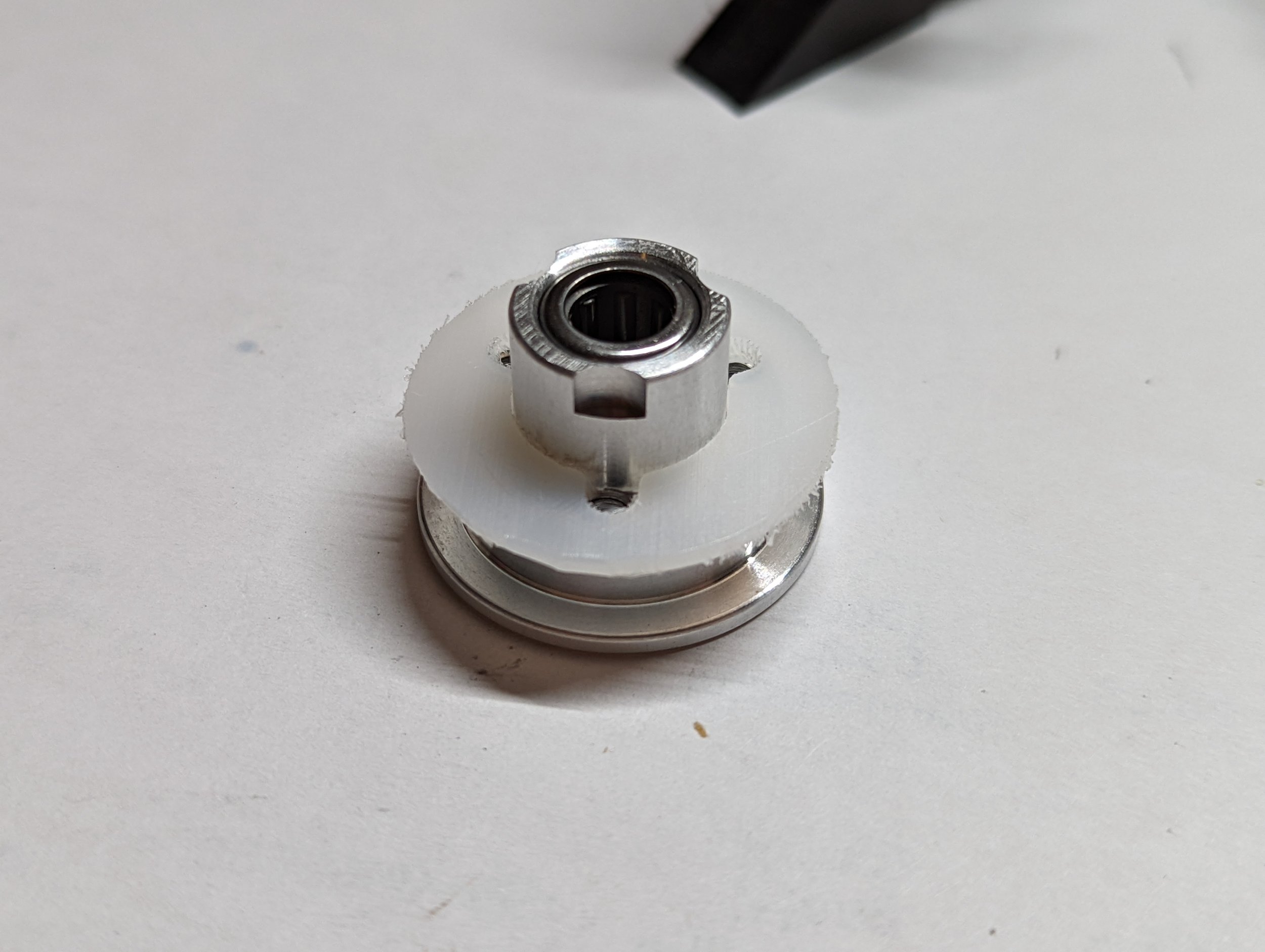
Weapon Hub Assembly:
If you buy a kit, this will already be done for you, Loctite and all! This is to show you how it is all put together for future maintenance.
On the weapon hub is a UHMW spacer to keep the belt spaced away from the blade.
The disc is made to be a snug fit on the hub, you may need to remove some of the paint with some sand paper to get the disc on the hub.
Next push the disc on as far as you can, then I use the 3 weapon bolts to draw the disc the rest of the way onto the hub. Go in a circle tightening each bolt maybe 1-2 turns at a time to work the disc onto the hub.
Once you get the bolts all the way in and the disc is snug against the UHMW washer and hub, take the bolts out, apply blue Loctite, and put the bolts back in.


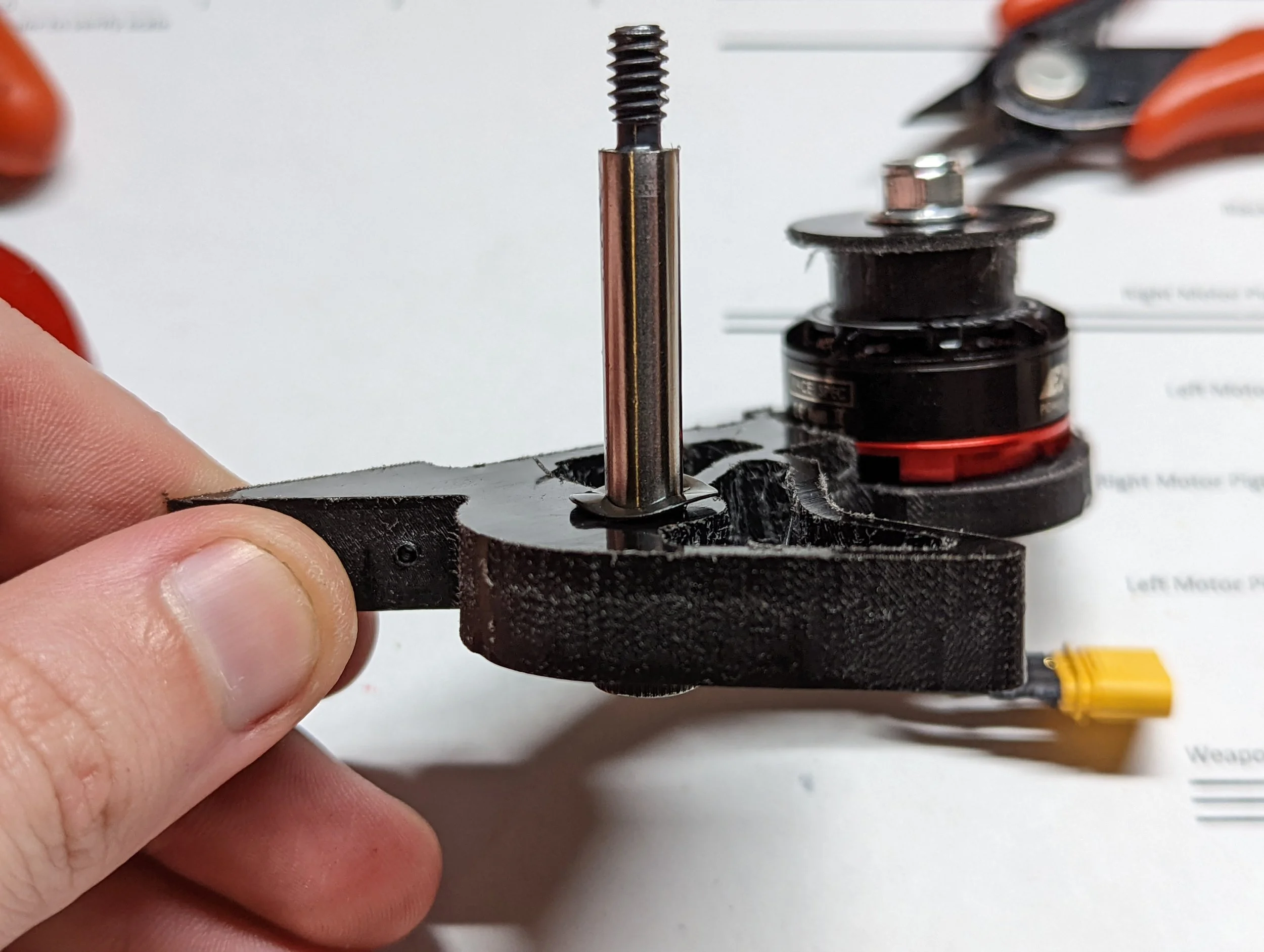
Center Section Assembly:
First insert your weapon shaft into the left side inner frame. Then place a thrust washer onto the shaft. (If you notice a sharp lip on one side of the washer, put that side up against the UHMW)
Then turn your Fingertech belt inside out and grab your weapon assembly.
You will need to pull your weapon shaft part way out of the inner frame, loop the belt around both pullies then place the weapon assembly onto the shaft.
Next push the weapon shaft back through the inner frame and all the way through weapon hub.
Now is when you can use some light bearing oil to lubricate the bearings. I use Dynamite Light Oil. Kits come pre lubricated.
Now place a second thrust washer onto the shaft, sharp lip up against the UHMW side frame you are about to put on.
Now place your right side inner frame on the shaft, and put your weapon shaft nut on. This nut should bottom out against the lip of the bolt.


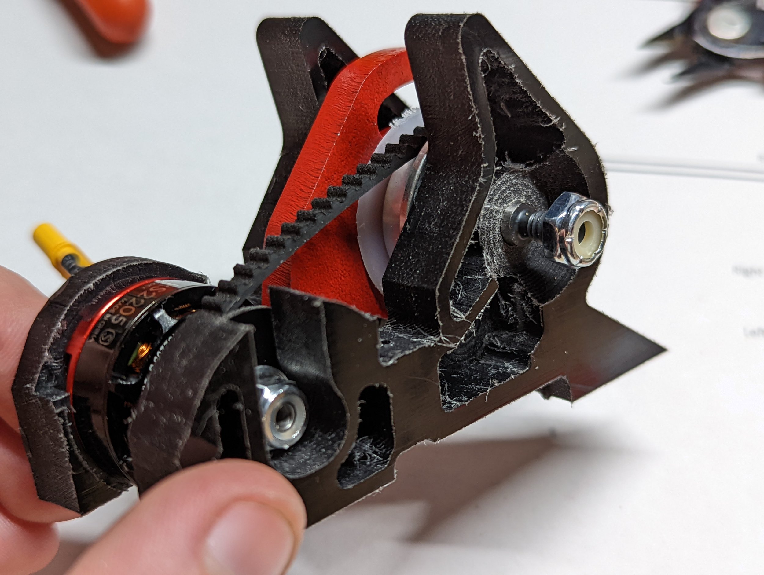

Center Section Assembly 2:
Now we need to insert the center assembly into the chassis. Pay close attention to avoid pinching your wires which run beneath your center section.
Note in the 4th image that the center section is not fully seated. Make sure the frame just behind the motor is fully seated, it should be flush with the top of the frame. This is critical in maintaining your weapon belt tension over a long period of time.
Next you can add your 4 countersunk screws in the base plate. tighten these until snug and flush with the chassis. It is possible to overtighten these and pull them through the chassis, don’t do that.


Wedge Assembly:
Place your wedge onto the front of the bot as shown. Use 4 countersunk screws and tighten until snug. Note that the lower screws will stick out the bottom of the frame slightly. I usually file these down a bit just to reduce the chance for them to get caught by a horizontal spinner.


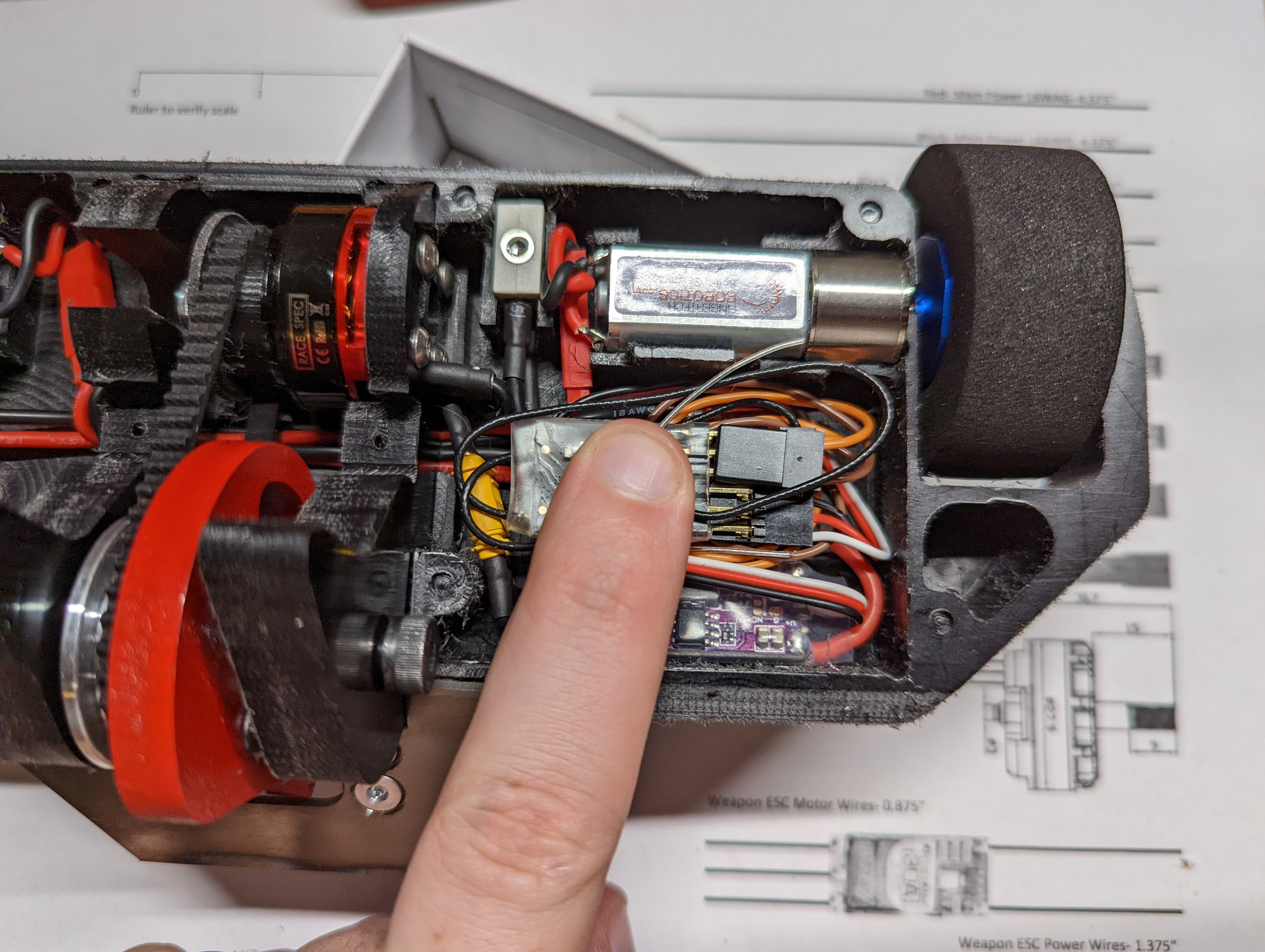
Weapon ESC and Receiver Install:
Next we need to put our weapon ESC into the bot. I like to tuck the weapon motor MR30 under the heat shrink of the weapon motor leads. Then you can orient the weapon esc as shown in the third image.
Next you can install your receiver. This is where this guide and your bot will diverge as you will be using your own receiver. Typically the weapon motor is plugged into Throttle(3) and your drive escs will be plugged into Aileron(1) and Elevator(2).
I will typically tape the antennas to the receiver and then put some more electrical tape around the connections to the receiver.
Next you can coil your wires beneath the receiver and place the receiver on top of the wires.
Now you can install your left side top plate.


Radio and Battery Ready!
Install your weapon lock! This will clip over the weapon motor and work in two ways, it will restrict the rotation of the weapon motor, and also prevent the disc tooth from passing by the weapon motor.
When you buy a Radio and Battery Ready Kit, this is what you receive!
(Minus the receiver, I included it above to show how I pack the wires around the receiver.)

